Cruise Controls & Autopilots: Tame control systems with a PID Loop

Cruse Control
Automatically control speed by updating throttle
You’re on “Monster Truck Battle Royale”, at your desk minding your own business, when your boss wakes you up. “Pssst! I got something for ya!… I. Need you. To build. Cruise control!!”. His boss asked if the monster trucks have cruise control, and they replied “OF COURSE they do.” So, now you gotta build a cruise-control before end-of-sprint review. Which, is tomorrow morning. And you’re hosting a dinner party tonight; the party starts in 4 hours. Dayum, whatcha gonna do now, punkin?
Just follow the steps here, and you’ll be fine.
So, first thing: write a user story. “As a user,” YARGGGHHH forget that!!! There’s no time!!! If the producers say you suck, then whateverrrr!!!!!
Down to brass tacks
Cruise Control:
| Monster Truck Variable | Control System Terminology |
|---|---|
| Current Speed | Process Variable (PV) |
| Target Speed | Setpoint (SP) |
| Throttle | Control Variable (CV) |
Will “open loop” control work?
Great question!
Open loop control is when you set a control variable without any feedback from a process variable… You drive the control variable directly using only the setpoint. You’re no doubt familiar with a number of examples, such as adjusting a toaster’s timer to hopefully yield the correct “done-ness”. Or, a 1980’s vehicle heater/air-conditioner. You’d turn a knob to make it warmer or colder but the actual temperature will vary with a number of other factors. “Climate Control” introduced closed-loop control, which meant finally holding the temperature at a setpoint.
The monster truck accelerator pedal is a form of open loop control. More throttle = more power, but the actual speed depends on many other factors such as the road’s incline. To maintain a particular speed we need “closed loop” control.
We’ll implement this in UE5, because… Well, it’s UE5.
Solution: PID Control Loop
There’s a “workhorse” solution for exactly these kinds of problems. Its enduring popularity is that it’s very easy to understand, and simple to implement. It’s called a “PID Loop” or “PID Controller”. If we can’t directly compute the control variable, we’ll just throw the problem at a PID loop and let the controller deal with it based on some tuning constants.
Stuff that’s often controlled by PID controllers:
- A vehicle’s cruise control.
- Temperature, flow rates, etc for HVAC, vehicle Air-Conditioning, etc.
- Aircraft auto-pilots
- Spacecraft “attitude” (orientation) in an Attitude Control System
- Servo-motor in a robotic arm
The math and terminology can look slightly intimidating for those who haven’t had calculus, but fear not. It’s highly intuitable.

All this means, is the control variable (throttle) is the sum of 3 simple terms:
- A “Proportional” constant (Kp) times the error value
- An “Integral” constant (Ki) times the total error accumulated over time.
- A “Derivative” constant (Kd) times the error’s rate-of-change.
Output = Kp * e + Ki * e_Accumulator + Kd * e_Rate;
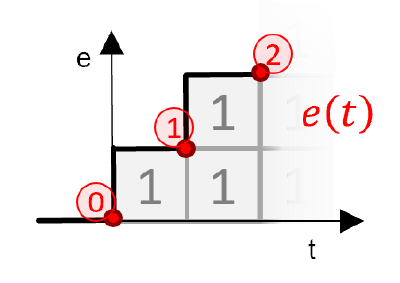
Proportional : Error Value Term
The first term in the PID equation is the Proportional term. To compute it, we need the error value, e, which the difference between the Setpoint (SP) and Process Variable (PV).

If we know the current error value, the ‘Proportional’ term will just be the product of e and the Proportional tuning constant, Kp.
    // Proportional term
    double e = SP - PV;
    Output += Kp * e;
Intuitively: The greater the error, the greater the output. Often this term provides the basic response, which the other terms fine tune.
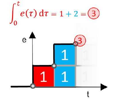
Integral : Total Accumulated Value
The next term is the Integral term. The error Integral term is just a fancy calculus way of saying the accumulated error (e) over time. So, at each time step we accumulate the current error (scaled by time). Multiply the current value times another tuning constant, Ki.
    // Integral term
    e_Accumulator += e * DeltaSeconds;
    Output += Ki * e_Accumulator;
Intuitively: The integral term, Ki, adds control variable output that zeros out error over the long term (if possible). This addresses situations where the Proportional term alone doesn’t quite hit the mark. As the error (e) accumulates, the control variable responds to neutralize it.
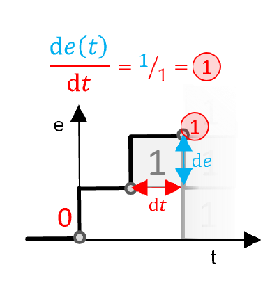
Derivative : Rate-Of-Change
And, Derivative is just the calculus way of saying “Rate of Change”. We can compute a simple rate of change as the difference in two values, divided by the time span that separates them.
    // Derivative term
    float e_Rate = (e - LastError) / DeltaSeconds;
    Output += Kd * e_Rate;
    LastError = e;
And, yada yada yada we multiply that by yet another tuning constant, you guessed it, Kd. The Derivative term is helpful for moderating the output to prevent it from overshooting and causing oscillations.
Intuitively: Kd responds to error change rate. So, if PV begins to depart the SP value but there isn’t yet much growth in the error, the derivate term will respond to resist the motion away from the setpoint value (SP). If the SP and PV are far apart the proportional term may respond over-zealously. We would use the derivative term to counter-act the Proportional Term’s overdrive for a more deliberate easing to the correct value, rather than an overshoot. This term dampens oscillatory responses.
And viola, the total CV Output is the sum of the “P”, “I”, and “D” terms.
    // Total Output term
    Output = (Kp * e) + (Ki * e_Accumulator) + (Kd * e_Rate);
In Unreal Engine
Since we’re making a cruise control, let’s start with the Unreal Engine Vehicle Game sample and control an actual vehicle. That’s more fun than watching raw numbers or charts, right?

We’ll try 3 different implementations of the PID loop, one pure C++, one that’s implemented in C++ but accessible to blueprints, and a third that’s implemented directly in blueprints.
Simple PID implementation in Pure UE C++
We’ll need three types of data - configuration (Kp, Ki, Kd), state (e_Accumulator, LastError), and a speed setpoint (SpeedSetpoint). The configuration data is static - known at build time. These values will be edited in the UE editor, serialized, and deserialized at runtime. This is unlike the state data, which will be dynamic & transient (not serialized), and perhaps in the setpoint’s case replicated.
Multiplayer Replication…?
In a server authoritative game we likely don’t need to run the PID loops on clients, the server is making all the decisions and the clients just see the result. The client could run PID loops in cases where it’s necessary for smoothly interpolating multiplayer movements. Or, a PID loop could be controlling something that’s mostly visual, locally, so it needs to run on the client.
In this case, we’re only going to run the PID loop on the server, and send updated setpoints from the clients via RPC.
| What | Type | Serialization | Replication |
|---|---|---|---|
| Config Data | Static | Serialized to/from Level | Not Replicated |
| State Data | Transient | Not Serialized | Not Replicated |
| Setpoint Values | Transient | Maybe | Possibly |
We have 3 categories of data behaviors. We’ll define structures for Config and State data, but keep any Setpoint values directly on the Actors - for ease of replication.
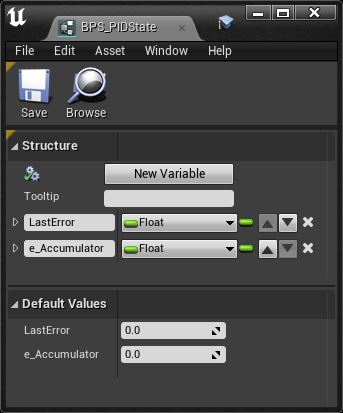
Structures
The state structure:
USTRUCT(BlueprintType)
struct FPIDState
{
    GENERATED_BODY()

    UPROPERTY(Transient) float LastError;
    UPROPERTY(Transient) float e_Accumulator;
};
Note that the Properties are Transient. UE does not need to store/restore either of these values, they’re truly transient.
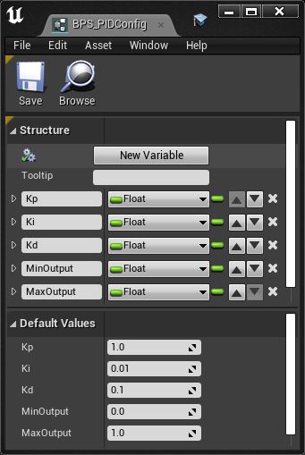
The config structure:
USTRUCT(BlueprintType)
struct FPIDConfig
{
    GENERATED_BODY()

    UPROPERTY(EditAnywhere, BlueprintReadWrite) float Kp;
    UPROPERTY(EditAnywhere, BlueprintReadWrite) float Ki;
    UPROPERTY(EditAnywhere, BlueprintReadWrite) float Kd;

    UPROPERTY(EditAnywhere, BlueprintReadWrite) float MinOutput;
    UPROPERTY(EditAnywhere, BlueprintReadWrite) float MaxOutput;
};
The editing permissions are set very liberally on this structure, because it will actually be the editing permissions on the actor that controls its editability.
Note the Min and Max Output values. Typically, there would be a signal transformation on both input (speed “Error”, e) and CV output (throttle setting). The error might be rescaled, perhaps with 0-200mph scaled and clamped into a 0-1 range. Similarly the output of the PID loop might be scaled clamped at 0-1 and then scaled 0-255 to the UE actor - or something. In the “real world” we might need to condition the signal by negating the sign, or apply a linear or logarithmic scaling etc.
We could generalize out example by adding input and output transformation UE delegates, etc for input/output transformations. But, why over engineer it already? It’s simple, let’s keep it simple. We can effectively scale the error input by scaling our loop tuning constants. Furthermore we can pick the constant values so as to scale the output into the 0-1 range. In your own implementation, just keep in mind you may wish to rescale both e (SP-PV) and Output (CV).
We WILL go ahead and clamp the output (CV) values, so we’ll include MinOutput and MaxOutput on the config.
It’s often useful to clamp the accumulated error value (e_Accumulator, in the state structure). Imagine a situation where the PID loop is controlling an aircraft yoke. The loop may have a small but non-zero “Integral” constant (Ki) to adjust the yoke if its not quite on target. Over time the error will accumulate and push the yoke into the correct position… Normally. But, what happens when the yoke’s full output cannot attain the process variable’s setpoint? The output would maintain full output, yet the error will not be eliminated. The error would accumulate over time and could reach very large values. Then, when it’s finally able for the process variable to attain the setpoint, the very large accumulated error term will dominate the PID loop and cause a full deflection until the accumulated error is finally reduced to within reason. In an aircraft, that would mean, say, if you set your climb rate unrealistically high, the error would accumulate over time. It could become very large, since the target climb rate (SP) exceeds the actual climb rate (PV). If the pilot then changes the setpoint for a zero climb rate, the accumulated error would then pull the yoke fully back (to climb) until the error term is eliminated. The yoke could be unresponsive and fully deflected for a considerable time. NOT GOOD!. This could also happen of the pilot adds power, the target climb rate will be exceeded while the integral term dissipates.
One fix is to clamp the accumulated error value such that the integral term cannot dominate the other terms. The situation above is a good reason to reset the PID loop accumulator when updating the setpoint. Another issue can be that the derivative term spikes upon changing setpoints, if the “LastError” value was relative to a different setpoint. This can be avoided by re-initializing the LastError value to a value relative to the new setpoint. We will provide a Reset method that resets the PID state as needed when the setpoint changes, etc.
PID Implementation Functions
Rather than pass SP and PV into the PID loop separately, the actor will pre-compute the error value, e, which is an input proxy for SP and PV.
Forward declarations for the update methods:
// ------------------------------------------------------------------------
// Method:    UpdatePID
//            Run the PIDController loop, update state values, and compute
//            loop CV output value.
// Returns:   float; PID Control loop output
// Qualifier:
// Parameter: const FPIDConfig &PIDConfig; PID Controller configuration
// Parameter: FPIDState &PIDState; PID Controller current state
// Parameter: float e; Error value (SP-PV)
// Parameter: float DeltaSeconds; Elapsed time, for derivatives & integrals
// ------------------------------------------------------------------------
PIDCONTROLLER_API float UpdatePID(const FPIDConfig& PIDConfig, FPIDState& PIDState, float e, float DeltaSeconds);

// ------------------------------------------------------------------------
// Method:    ResetPID
//            Resets PID State derivative and integral intermediates.
//            This is useful to avoid loop ill behavior across setpoint
//            (SP) discontinuities.
// Returns:   void
// Qualifier:
// Parameter: FPIDState &PIDState; PID Controller current state
// Parameter: float NewErrorValue; value of e(T(N-1)) for next timestep
//            T(N).  The next time the error derivative is computed, the
//            initial value for e of this timestep will be NewErrorValue.
// Parameter: float NewAccumulatorValue; New Integral, accumulated error
//            through current time (t)
// ------------------------------------------------------------------------
PIDCONTROLLER_API void ResetPID(FPIDState& PIDState, float NewErrorValue, float NewAccumulatorValue = 0.f);
Note that the code above assumes the code lives in a UE module named “PidController”, because it uses the module import/export macro PIDCONTROLLER_API.
UpdatePID will, obviously, run the PID loop per the config and state, then return an output float CV to the caller. ResetPID will be used when updating the setpoint, to flush stale accumulator and rate-related values.
The PID loop is a simple, straight-forward implementation:
// ------------------------------------------------------------------------
// Method:    UpdatePID
//            Run the PIDController loop, update state values, and compute
//            loop CV output value.
//            (See additional comments in PID.h)
// ------------------------------------------------------------------------
float UpdatePID(const FPIDConfig& PIDConfig, FPIDState& PIDState, float e, float DeltaSeconds)
{
    check(DeltaSeconds > 0.f);

    float Output = 0.f;

    // Proportional term
    Output += PIDConfig.Kp * e;

    // Integral term
    PIDState.e_Accumulator += e * DeltaSeconds;
    Output += PIDConfig.Ki * PIDState.e_Accumulator;

    // Derivative term
    float e_Rate = (e - PIDState.LastError) / DeltaSeconds;
    Output += PIDConfig.Kd * e_Rate;
    PIDState.LastError = e;

    return FMath::Clamp(Output, PIDConfig.MinOutput, PIDConfig.MaxOutput);
}
And there’s not much to the reset:
// ------------------------------------------------------------------------
// Method:    ResetPID
//            Resets PID State derivative and integral intermediates.
//            This is useful to avoid loop ill behavior across setpoint
//            (SP) discontinuities.
//            (See additional comments in PID.h)
// ------------------------------------------------------------------------
void ResetPID(FPIDState& PIDState, float NewErrorValue, float NewAccumulatorValue)
{
    PIDState.LastError = NewErrorValue;
    PIDState.e_Accumulator = NewAccumulatorValue;
}
Changes to the existing pawn (BuggyPawn)
In UE’s architecture, the easiest integration path is to just derive a new Pawn from the example’s ABuggyPawn:
PIDBuggyPawn.h
#pragma once

#include "BuggyPawn.h"
#include "PID.h"
#include "PIDBuggyPawn.generated.h"


// ------------------------------------------------------------------------
// Method:    FPIDConfig
//            Contains static configuration data for one type of PID Loop.
//            Can be shared across multiple loops that share dynamics
//            and desired behaviors.
// ------------------------------------------------------------------------
UCLASS(BlueprintType)
class PIDBUGGY_API APIDBuggyPawn : public ABuggyPawn
{
    GENERATED_BODY()

public:
    APIDBuggyPawn();

protected:
    UPROPERTY(VisibleInstanceOnly, BlueprintReadWrite, Category = PID)
    uint32 bRunCppPID : 1;

    UPROPERTY(Category = PID, EditDefaultsOnly, BlueprintReadWrite)
    FPIDConfig PIDConfig;

    UPROPERTY(Category = PID, Transient, VisibleInstanceOnly, BlueprintReadOnly)
    FPIDState PIDState;

    UPROPERTY(Category = PID, Replicated, EditDefaultsOnly, BlueprintReadWrite)
    float SpeedSetpoint = 1000.f;

public:
    void Tick(float DeltaSeconds) override;
    void SetupPlayerInputComponent(UInputComponent* PlayerInputComponent) override;

protected:
    void IncreaseSpeedSetpoint();
    void DecreaseSpeedSetpoint();

    UFUNCTION(Server, Reliable, WithValidation)
    void RPC_IncreaseSpeedSetpoint();
    UFUNCTION(Server, Reliable, WithValidation)
    void RPC_DecreaseSpeedSetpoint();
};
Note the code above uses another module import/export macro, PIDBUGGY_API… Because this code lives in a module named “PIDBuggy”.
PIDBuggyPawn.cpp:
#include "PIDBuggyPCH.h"
#include "PIDBuggyPawn.h"
#include "WheeledVehicleMovementComponent.h"
#include "UnrealNetwork.h"

APIDBuggyPawn::APIDBuggyPawn()
{
    PIDConfig.Kp = 0.005f;
    PIDConfig.Ki = 0.0003f;
    PIDConfig.Kd = 0.00006;
    SpeedSetpoint = 1000.f;
}


void APIDBuggyPawn::Tick(float DeltaSeconds)
{
    Super::Tick(DeltaSeconds);

    //	UE_LOG(LogTemp, Log, TEXT("Speed = %f"), GetVehicleSpeed());

    UWheeledVehicleMovementComponent* VehicleMovementComp = GetVehicleMovementComponent();
    // Run the PID loop to update the throttle (server, for physics, and client, for throttle visual effects)
    if (VehicleMovementComp != nullptr)
    {

        float Error = SpeedSetpoint - GetVehicleSpeed();
        float ThrottleOutput = UpdatePID(PIDConfig, PIDState, SpeedSetpoint - GetVehicleSpeed(), DeltaSeconds);

        VehicleMovementComp->SetThrottleInput(ThrottleOutput);

        // UE_LOG(LogTemp, Log, TEXT("Speed = %f, ThrottleOutput = %f"), GetVehicleSpeed(), ThrottleOutput);
    }
}

void APIDBuggyPawn::SetupPlayerInputComponent(UInputComponent* PlayerInputComponent)
{
    Super::SetupPlayerInputComponent(PlayerInputComponent);

    PlayerInputComponent->BindAction("IncreaseSpeedSetpoint", IE_Pressed, this, &APIDBuggyPawn::IncreaseSpeedSetpoint);
    PlayerInputComponent->BindAction("DecreaseSpeedSetpoint", IE_Pressed, this, &APIDBuggyPawn::DecreaseSpeedSetpoint);
}

void APIDBuggyPawn::IncreaseSpeedSetpoint()
{
    // Send speed setpoint request to server
    RPC_IncreaseSpeedSetpoint();
}

void APIDBuggyPawn::DecreaseSpeedSetpoint()
{
    // Send speed setpoint request to server
    RPC_DecreaseSpeedSetpoint();
}

void APIDBuggyPawn::RPC_IncreaseSpeedSetpoint_Implementation()
{
    SpeedSetpoint += 100.f;
    SpeedSetpoint = FMath::Clamp(SpeedSetpoint, 0.f, 3000.f);

    if (GEngine)
        GEngine->AddOnScreenDebugMessage(-1, 4.0f, FColor::Green, FString::Printf(TEXT("Speed setpoint increased to %f"), SpeedSetpoint));
}

bool APIDBuggyPawn::RPC_IncreaseSpeedSetpoint_Validate()
{
    return true;
}

void APIDBuggyPawn::RPC_DecreaseSpeedSetpoint_Implementation()
{
    SpeedSetpoint -= 100.f;
    SpeedSetpoint = FMath::Clamp(SpeedSetpoint, 0.f, 3000.f);

    if (GEngine)
        GEngine->AddOnScreenDebugMessage(-1, 4.0f, FColor::Red, FString::Printf(TEXT("Speed setpoint decreased to %f"), SpeedSetpoint));
}

bool APIDBuggyPawn::RPC_DecreaseSpeedSetpoint_Validate()
{
    return true;
}

void APIDBuggyPawn::GetLifetimeReplicatedProps(TArray< FLifetimeProperty >& OutLifetimeProps) const
{
    Super::GetLifetimeReplicatedProps(OutLifetimeProps);

    DOREPLIFETIME(APIDBuggyPawn, SpeedSetpoint);
}
And with that, we’re ready to roll…
Loop tuning
The good news is that PID loops are very simple, yet powerful and applicable to a wide variety of situations.
Do you want the bad news?
Tuning PID loops can be a frustrating, hairy, counter-intuitive exercise that’s difficult to teach. You just have to tinker with various control systems and tuning constants to develop a little bit of instinct.
Designing and tuning a PID controller appears to be conceptually intuitive, but can be hard in practice, if multiple (and often conflicting) objectives, such as short transient and high stability, are to be achieved. PID controllers often provide acceptable control using default tunings, but performance can generally be improved by careful tuning, and performance may be unacceptable with poor tuning.
PID_controller: Wikipedia
Even worse, a set of PID constants that work on one scenario may completely break in another. Imagine something like a aircraft or spacecraft that consumes fuel as it goes, changing its Moment of Inertia. PID constants that work with a full fuel tank may start to misbehave as the fuel burns due the differing responses of the process variable to controls.
If you plan to tune PID loops you’ll want to find some online reference material to review. My normal approach is to set all terms to zero, then try a few reasonable values for Kp until I get the rough response desired and a slight “overshoot” of the target. I’ll then add a very small Kd to reduce the overshoot. And only if there’s a bit of steady-state error do I add some Ki to give the output a final nudge that attains the correct PV value.
Testing the Loop
Once we’ve tuned the P, I, and D values to generate an acceptable response, our cruise-control holds the vehicle’s speed at the setpoint (more or less) regardless of the transmission gear ratio, etc.
Cruise Control in action
As you can see in the embedded video, the PID Loop works the throttle to achieve and hold the target speed…. regardless of the current terrain inclination, traction, or transmission gear, etc.
Simple PID implementation:
Exposing C++ implementation to Blueprints users
A CPP implementation accessible by Blueprints is just a matter of ensuring the structures are marked as BlueprintType in their USTRUCT() declaration, and wrapping the function calls into a BlueprintFunctionLibrary.
Here, we define a Blueprint Function Library to contain the two implementations:
#pragma once

#include "PID.h"
#include "BPPIDLibrary.generated.h"

UCLASS()
class PIDCONTROLLER_API UBPPIDLibrary : public UBlueprintFunctionLibrary
{
    GENERATED_UCLASS_BODY()

    // ------------------------------------------------------------------------
    // Method:    UpdatePID
    //            Run the PIDController loop, update state values, and compute
    //            loop CV output value.
    // Returns:   float; PID Control loop output
    // Qualifier:
    // Parameter: const FPIDConfig &PIDConfig; PID Controller configuration
    // Parameter: FPIDState &PIDState; PID Controller current state
    // Parameter: float e; Error value (SP-PV)
    // Parameter: float DeltaSeconds; Elapsed time, for derivatives & integrals
    // ------------------------------------------------------------------------
    UFUNCTION(BlueprintCallable, Category = "PID")
    static void UpdatePID(float& LoopOutput, UPARAM(ref) FPIDState& PIDState, const FPIDConfig& PIDConfig, float e, float DeltaSeconds);

    // ------------------------------------------------------------------------
    // Method:    ResetPID
    //            Resets PID State derivative and integral intermediates.
    //            This is useful to avoid loop ill behavior across setpoint
    //            (SP) discontinuities.
    // Returns:   void
    // Qualifier:
    // Parameter: FPIDState &PIDState; PID Controller current state
    // Parameter: float NewErrorValue; value of e(T(N-1)) for next timestep
    //            T(N).  The next time the error derivative is computed, the
    //            initial value for e of this timestep will be NewErrorValue.
    // Parameter: float NewAccumulatorValue; New Integral, accumulated error
    //            through current time (t)
    // ------------------------------------------------------------------------
    UFUNCTION(BlueprintCallable, Category = "PID")
    static void ResetPID(UPARAM(ref) FPIDState& PIDState, float NewErrorValue, float NewAccumulatorValue = 0.f);
};
Again, note the module-specific import/export macro, PIDCONTROLLER_API. In this example the two Blueprint Actions (UpdatePID and ResetPID) can juse lean on the native C++ implementations:
#include "PIDPCH.h"
#include "BPPIDLibrary.h"
#include "PID.h"

// ------------------------------------------------------------------------
// Even though we did not declare this constructor, we have to define it
// or UE tells the compiler to scream and yell at us, and we don't want
// that.
// ------------------------------------------------------------------------
UBPPIDLibrary::UBPPIDLibrary(const FObjectInitializer& ObjectInitializer) : Super(ObjectInitializer)
{
}


// ------------------------------------------------------------------------
// Method:    UpdatePID
//            Run the PIDController loop, update state values, and compute
//            loop CV output value.
//            (See additional comments in BPPIDLibrary.h)
// ------------------------------------------------------------------------
void UBPPIDLibrary::UpdatePID(float& LoopOutput, FPIDState& PIDState, const FPIDConfig& PIDConfig, float e, float DeltaSeconds)
{
    // Fully qualify callee with namespace to disambiguate it from this.
    LoopOutput = stupidGameDevTricks::UpdatePID(PIDConfig, PIDState, e, DeltaSeconds);
}


// ------------------------------------------------------------------------
// Method:    ResetPID
//            Resets PID State derivative and integral intermediates.
//            This is useful to avoid loop ill behavior across setpoint
//            (SP) discontinuities.
//            (See additional comments in PID.h)
// ------------------------------------------------------------------------
void UBPPIDLibrary::ResetPID(FPIDState& PIDState, float NewErrorValue, float NewAccumulatorValue)
{
    // Fully qualify callee with namespace to disambiguate it from this.
    stupidGameDevTricks::ResetPID(PIDState, NewErrorValue, NewAccumulatorValue);
}
To use this implementation from blueprints, the Blueprint Buggy Actor declares PIDState, PIDConfig, and SpeedSetpoint variables. Then, the pawn’s Tick function is Tick function will run the UpdatePID action and send the result into the throttle control. See the below usage of the Blueprint-only implementation for more info.
I’m happy to throw the project onto GitHub if it’s helpful to anyone (just drop me an email). The whole project, content and all is over 1gb, but the source code itself is obviously a small fraction.
Simple PID implementation:
100% Blueprint Implementation
As you’ve seen, PID loop implementations are simple, just a few additions, multiplications, a subtraction, and a division. There is nothing magic that can’t be done directly in blueprints themselves.
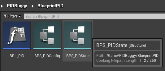
For a 100% native blueprints implementation, we’ll need to create UE assets for a Blueprint Function Library (BPL_PID), as well as structures for both the config and state (BPS_PIDConfig, and BPS_PIDState):
The UpdatePID action will be defined in the Blueprint Function Library. It will have 3 main blocks:
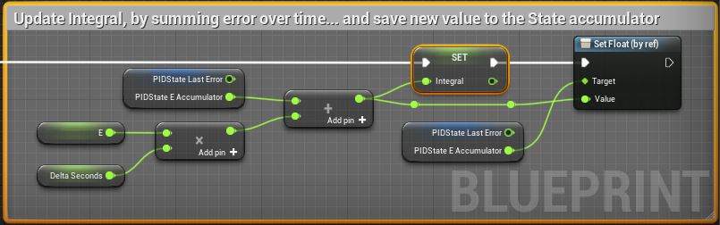
- Compute the Integral value, and update the integral accumulator state.
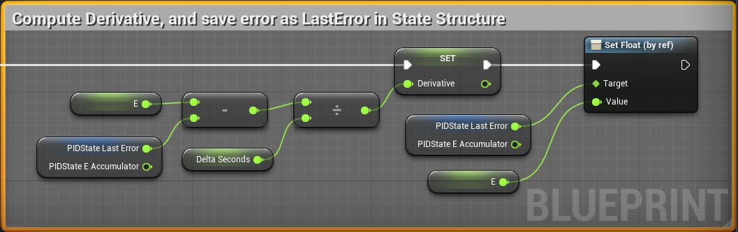
- Compute the Derivative value, update the error state value.
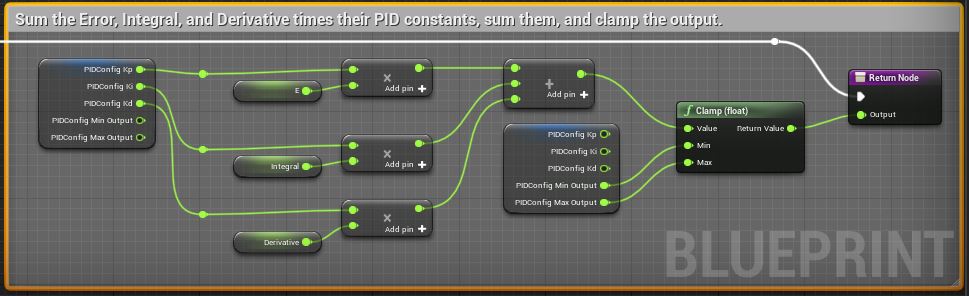
- Multiply and add the terms for Proportion, Integral, and Derivative to compute the CV Output.
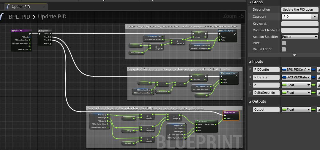
A more detailed view of the 3 blocks above:
The ResetPID action couldn’t be simpler:
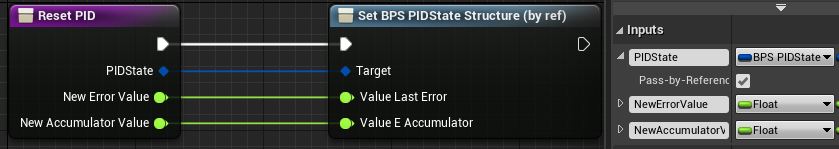
Note that the state structure is passed by reference, so it can be updated.
That completes the PID implementation itself, 100% in Blueprints.
To actually use the implementation, we’ll need to wire it into our monster truck’s Buggy Blueprint:
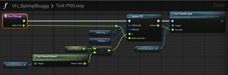
Creating the Cruise Control is simply a matter of computing the Error value, e, as SP - PV. In this case, the Process Variable can be obtained from the Vehicle Movement component, and the GetForwardSpeed action. Then, the PID config and state are passed to the Update PID action, which returns an output CV which can be passed to the vehicle movement component’s throttle input value via the SetThrottleInput value.
Simple, right? All except for the loop tuning. This version of the loop functions the same as the native C++ version above - they’re identical algorithms just implemented at different layers. And with that exercise complete, you have a dinner party to host!
Cascade Control
In many cases, two PID controllers can provide superior control over a Process Variable where a single PID loop would struggle. A particular case to note is Spacecraft Attitude Control.
Spacecraft Attitude Control
Consider a spacecraft’s attitude control system. There are many times you may wish to hold the spacecraft at a particular orientation:
- For navigation purposes, to apply thrust in a particular direction.
- For instrumentation purposes, such as pointing a camera at something you wish to image.
- For communications reasons, to point an antenna at a recipient such as the Deep Space Network.
- For energy management reasons, such as ensuring maximum illumination on your solar panels.
In this case, our process variable is the spacecraft’s orientation, we’ll call it yaw, pitch, and roll. Our control variable is a means of producing torque (reaction wheels, cold gas thrusters, gimble angle, etc). Torque can directly manipulate the object’s angular velocity over time. But, we wish to control the angular position not angular velocity. This is a “second order” system, because equations describing it contain not just the process variable’s derivative/rate-of-change (angular velocity), but it’s derivative as well (angular acceleration) through the control variable.
This is a case readily handled by two PID loops arranged in a cascade:
- “Outer Loop”
- PV: Angular Position
- CV: Angular Velocity
- “Inner Loop”
- PV: Angular Velocity
- CV: Torque Output
The outer loop tracks a position setpoint, and outputs a desired angular velocity to minimize the PV error.
The inner loop tracks the angular velocity “cascaded” setpoint from the outer loop, to apply torque that achieves the requested angular velocity.
As example code, the block below attains a target pitch and roll, while holding the yaw rate at 0. In this case we are “pointing” the spacecraft’s primary axis at a target. Yet, the Spacecraft can rotate around the primary axis - all the control system does is minimize the rotation rate.
Simple cascaded closed loop satellite pointing simulation:
FSAngularVelocity av;
...

// Assuming the target rate for each axis is zero, initialize the current error as the negated
// Angular rate around each axis...
float YawRateError   = -(float)av.z.AsRadiansPerSecond();
float PitchRateError = -(float)av.y.AsRadiansPerSecond();
float RollRateError  = -(float)av.x.AsRadiansPerSecond();

// Determine if the outer control loops control pointing
if (IsOrientationControlling())
{
    FSAngle RollError, PitchError;

    // Compute Pitch & Roll Errors based on current orientation
    PitchRoll(PrimaryAxisTarget, AngularState, PitchError, RollError);

    // Run the outer loops, which output a target rate based on current orientation delta (Pitch/Roll Error)
    // Adjust the inner loop Pitch/Roll rate setpoints (via the error) based on outer loop
    PitchRateError += PitchLoopState.Update(PitchRollConfig, normalizePiToPi(PitchError.AsRadians()), DeltaTime);
    RollRateError += RollLoopState.Update(PitchRollConfig, normalizePiToPi(RollError.AsRadians()), DeltaTime);
}

// Run the inner control loops to obtain the axis control values.
ControlOutputYaw   = FromRadsPerSec(YawLoopRateState.Update(PitchRollRateConfig, YawRateError, DeltaTime));
ControlOutputPitch = FromRadsPerSec(PitchLoopRateState.Update(PitchRollRateConfig, PitchRateError, DeltaTime));
ControlOutputRoll  = FromRadsPerSec(RollLoopRateState.Update(RollRateConfig, RollRateError, DeltaTime));
In the case above, if IsOrientationControlling() evaluates to false, the 3 inner controllers are driven to eliminate any angular velocity. If the term evaluates to true, the outer control loops are engaged, which drive the pitch/roll axes to point the primary axis in the direction of a target (the sun, earth, camera target, etc). The yaw axis continues to seek zero rotation rate, but does not seek any particular rotational position. Actual spacecraft, of course, often hold a non-zero rotation rate when utilizing ‘spin stabilization’. Note that the “Primary Axis” is generally the Z+ axis in the Satellite Body Reference Frame (SBRF), and can vary depending on the most important axis of the satellite (camera, science instrument, antenna, solar panels, primary thrust, etc).
I’ll post an example to github if I get a chance (and update to add a link here). Or, do you have an example you’d like to share? Send a link :-D.
